01 — Stepper Controller

Stepper Motor Controller
for Precise Wheel Steering

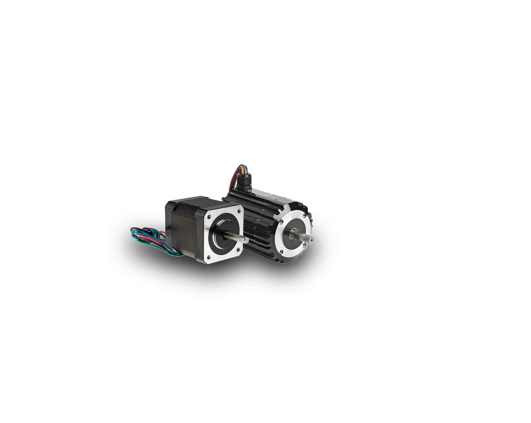
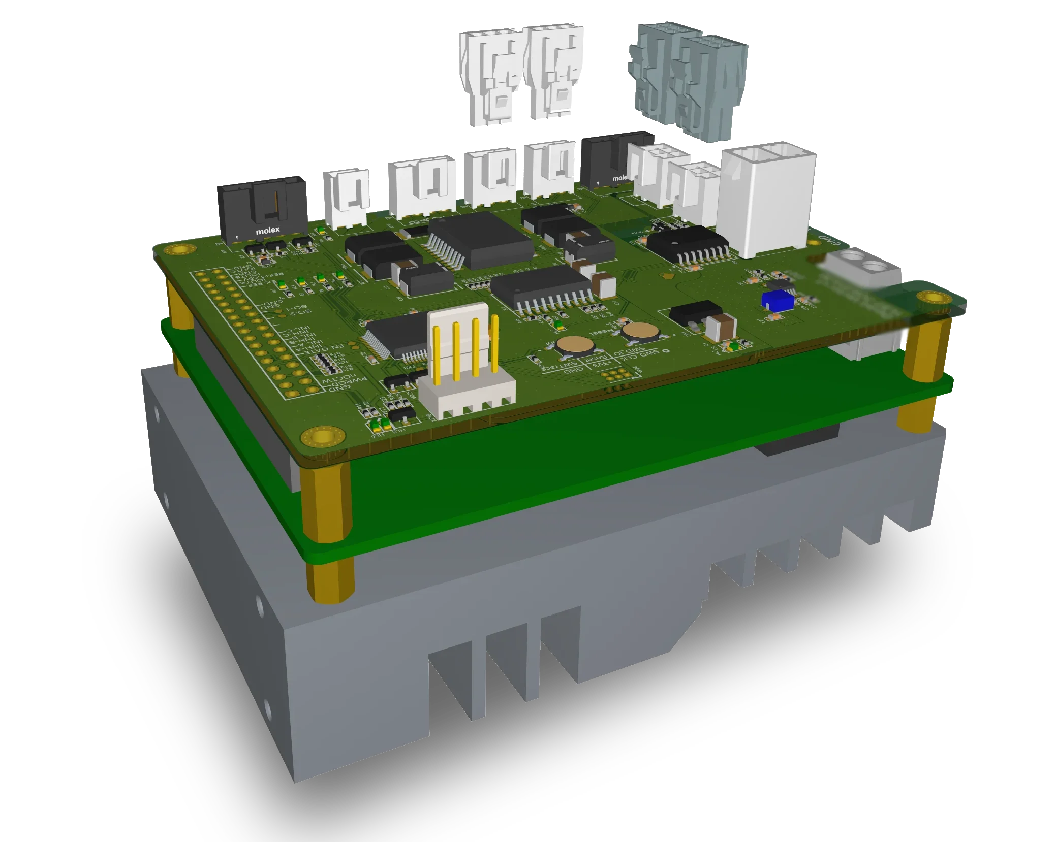
Within the Mobile Robot project, for motor wheel block steering, a Stepper Motor Controller was developed for precise control of the stepper motor.

The L297 has been selected due to chip shortage.

The STM32F303 receives commands from the robot’s main controller and generates the phase control sequence for stepper drive via L297+298. ISO1450 provides galvanic isolation for RS-485 communication between the STM32F303 and other robot modules.

To optimize the thermal operating conditions and maximize the power output of an obsolete controller, a fan was mounted on a massive heatsink with cutouts for oversized components. During steering, the driver was temporarily pushed to critical current levels, while a reduced-current mode was used for holding torque.
Stepper Motor Controller PCB
02 — Power Quality Monitor

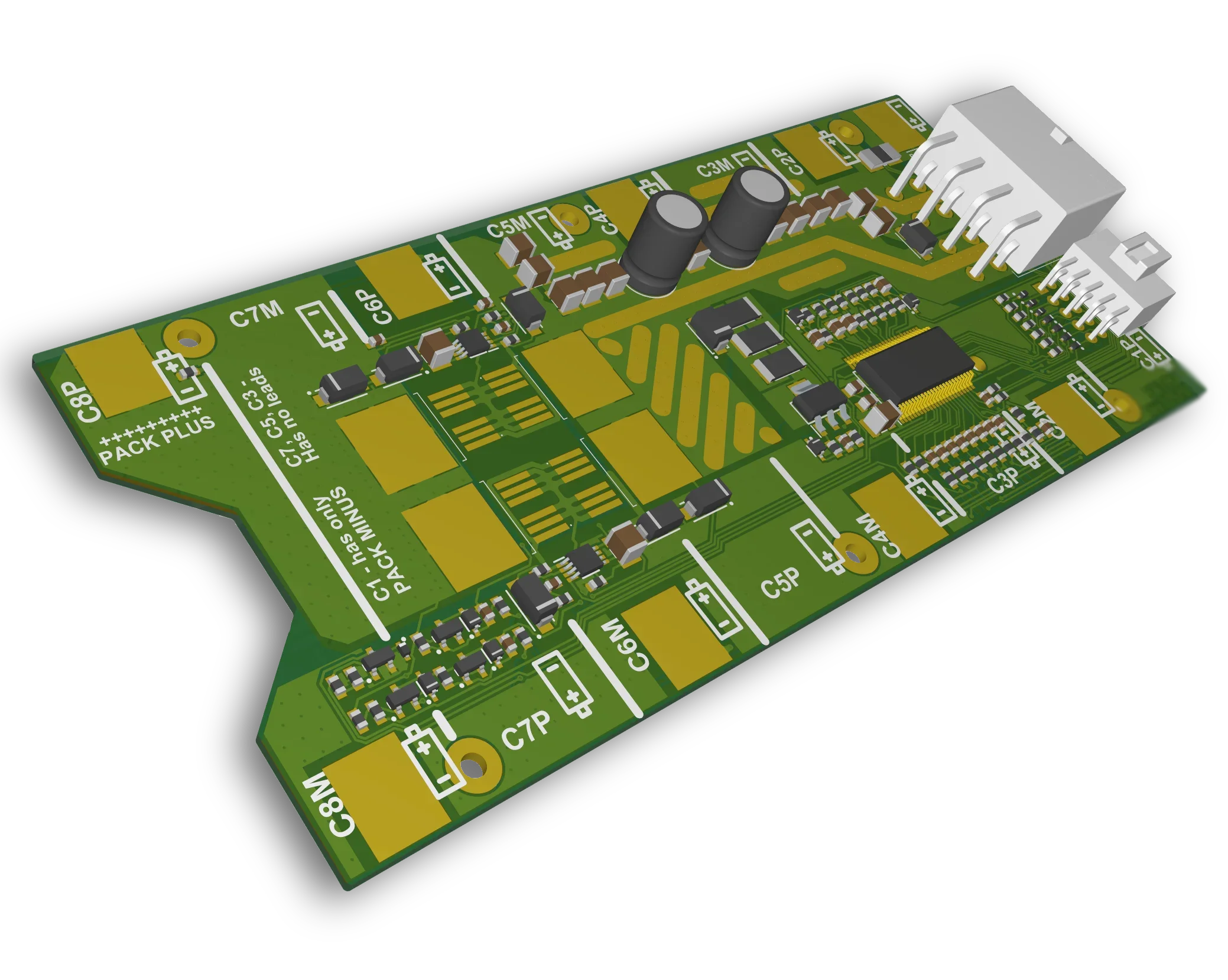
Advanced Power Quality
Monitoring System

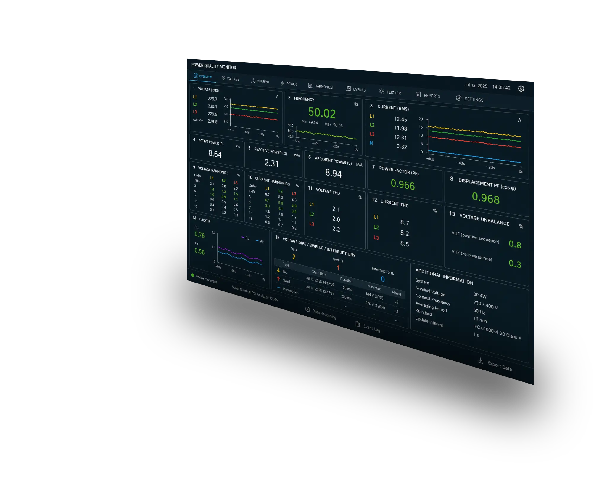
Three-Phase Power Quality Measurement Module for a Digital Substation Computer.

The STM32F746 microcontroller is placed on the hot side of the isolation barrier to enable real-time data processing and control directly interfacing with power lines. This decision was made to ensure the system can handle real-time data effectively while maintaining compatibility with existing isolation components and ensuring safe communication across isolated domains.

The STM32F746 microcontroller and 5CEBA2 FPGA collaborate to provide high-speed data processing and custom logic implementation for power quality monitoring. The STM32F746 processes measurement data and transfers it through the ADUM1401 digital isolator to the FPGA. The FPGA converts the parallel interface to LVDS and transmits the data to the processor board over the cross-board connection.

To maintain isolation integrity and reduce noise, the ADUM1401 digital isolator was placed directly between the STM32F746 and the 5CEBA2 FPGA, minimizing trace lengths and ensuring a clear separation from high-frequency components.

Power Quality Monitoring PCB
03 — Central Control

Central Control Motherboard
for Mobile Robot

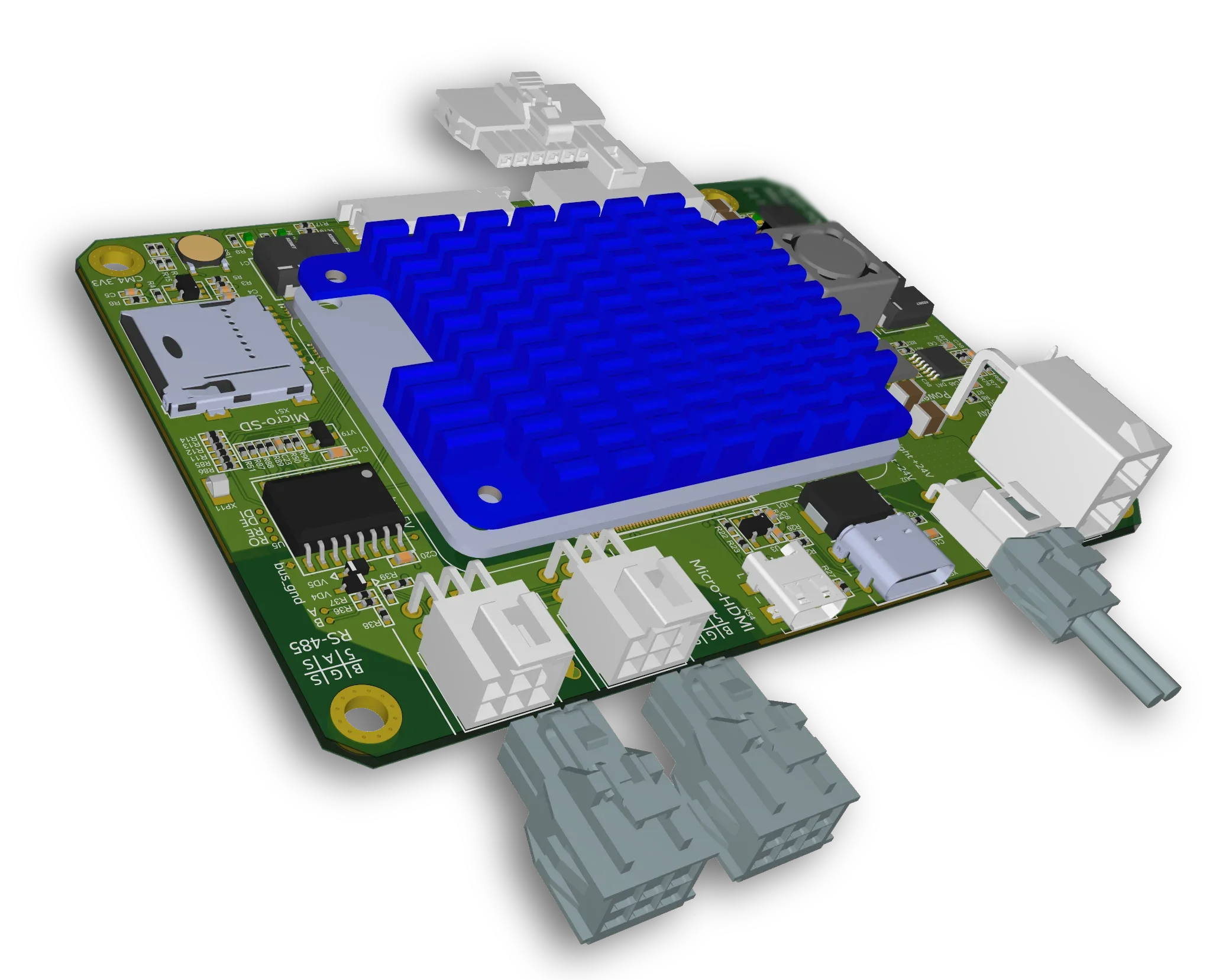
Within the Mobile Robot project, for designing a central control motherboard for RPi CM4. The Motherboard was developed for managing and controlling the robot's peripheral systems.

The LM3150 was selected for a custom high-current buck converter powering the motherboard. Its controller-based architecture allowed both the power stage and the compensation network to be adapted to the electrical characteristics of the board.

Particular attention was paid to high-speed PCB layout, including ESD protection, controlled-impedance routing, reference plane continuity, and length matching for USB and HDMI interfaces.

Central Control Motherboard PCB
04 — Wi-Fi Bridge

Wi-Fi Bridge
for Mobile Robot MVP

Within the Mobile Robot MVP project, for managing the Wi-Fi connection, a Wi-Fi Bridge was developed to enable wireless communication for the central control module.

The decision to integrate the ESP32-WROOM-32E for Wi-Fi connectivity and SN75176BDR for RS-485 compatibility was made because the ESP32 allows faster development and maintains compatibility with the existing RS-485 infrastructure. Quick integration using available components was necessary to meet project deadlines.

Wi-Fi Bridge PCB
05 — Prototyping Motherboard

Fast Prototyping Motherboard
for Mobile Robot

Within the Mobile Robot MVP project, for fast connection of peripherals to the Nucleo board, the Fast Prototyping Motherboard was developed to enable rapid integration of motors, sensors, and modules for mobile robot development.

The STM32H743-NUCLEO was utilized for its rapid prototyping capabilities, allowing quick demonstration of functionality using existing components without the need for new hardware development. This decision was constrained by the requirement to integrate legacy control of the VNH3SP30 without developing a new driver.

The STM32H743-NUCLEO board supports rapid prototyping by allowing quick integration of sensors and motor drivers. It facilitates the connection of the VNH3SP30 motor driver and the ICM-20602 motion sensor, enabling efficient control and motion tracking. The ICM-20602 is used for real-time orientation correction of the robot.

Thick copper layers were used to carry high motor currents within the limited PCB area while maintaining acceptable temperature rise.

Fast Prototyping Motherboard PCB
06 — Motor Control System

Motor Control System
for Steering & Drive

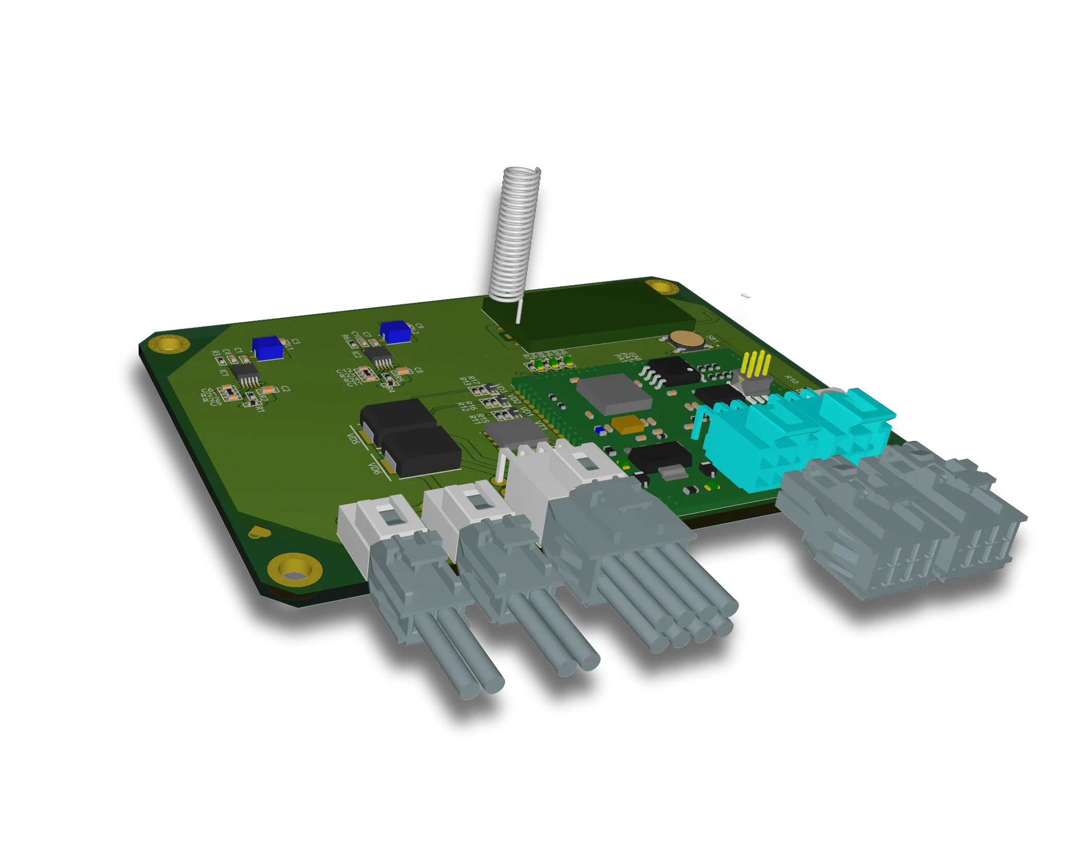
The STM32F303 receives motion commands from the robot's main controller and coordinates the steering and drive subsystems. The UCC2626 controls the brushless drive motor, while the L6480 drives the steering stepper motor.

The BLDC controller is built around the UCC2626 Hall-sensor commutation controller, with the surrounding analog circuitry implementing the complete speed control loop. The analog stages perform speed error amplification, bidirectional command processing, PWM generation, Hall sensor conditioning, and current limiting before driving the three-phase power stage.

Motor Control System PCB
07 — Emergency Breaker

RF-Controlled Emergency
Breaker

Within the Mobile Robot project, for the task of shutdown on emergency and keeping power supply, an RF-controlled emergency breaker was developed to ensure power supply continuity to critical modules during emergencies of the battery management module.

BSC066 was chosen for its availability and compatibility with existing designs, as it has proven reliability in similar applications and helps avoid redesign costs. The decision was constrained by the need for compatibility with existing designs and a quick development cycle.

The LT8609 provides voltage regulation, converting the 12V power bus to lower voltages, while the BSC066 manages power switching. Together, they efficiently manage power in the robot's circuits. One LT8609 exclusively powers the battery management module and shut it down on RF signal, while another keeps supplying critical modules.

The power distribution layout was optimized to reduce voltage disturbances caused by emergency disconnection of high-power loads.

RF-Controlled Emergency Breaker PCB
08 — Universal SMT Module

Small-Size Universal
SMT Module

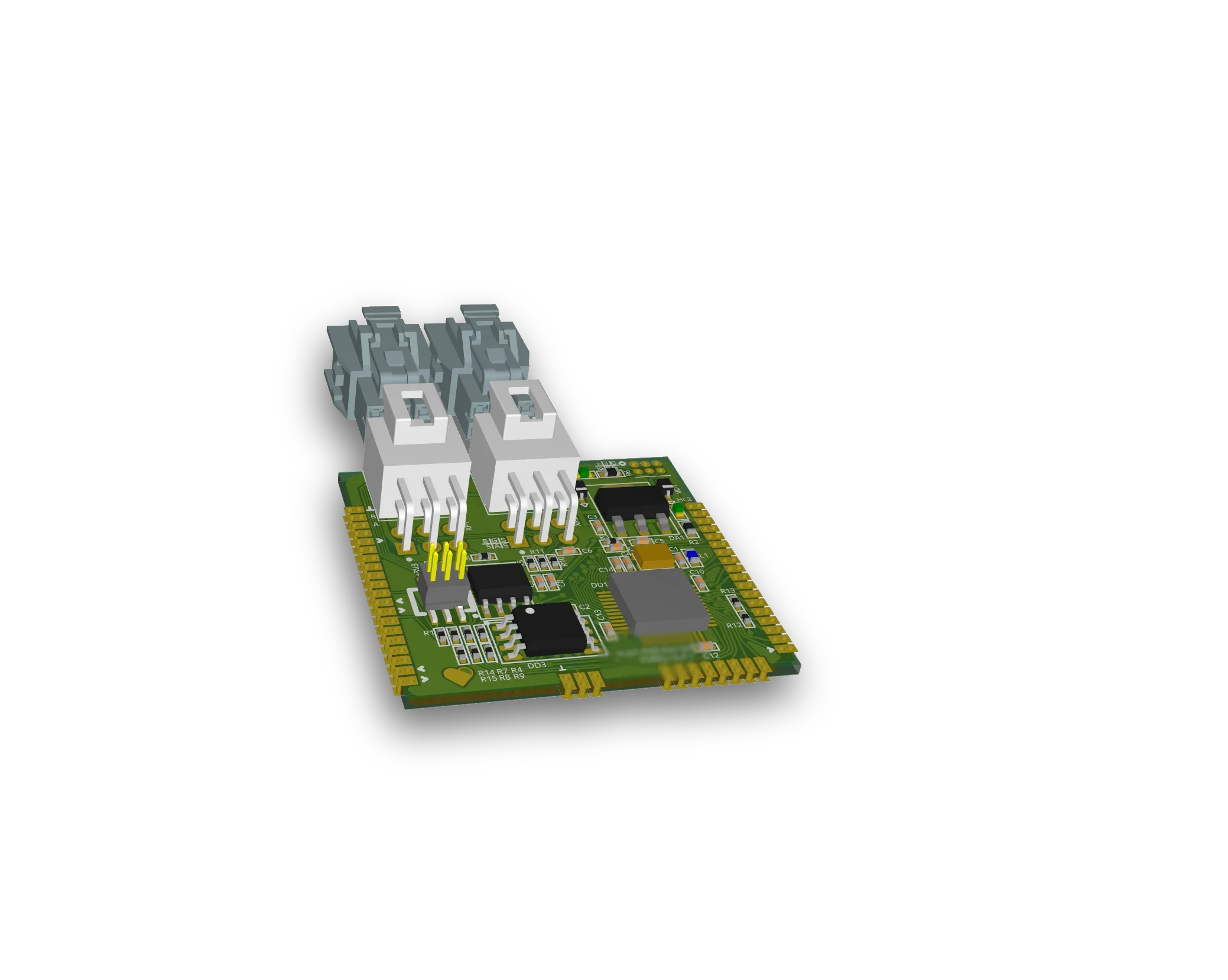
Within the Mobile Robot project, for the task of developing a small-size universal SMT Module, a device was developed to facilitate communication and control for any peripheral board of the robot.

The STM32F303 microcontroller manages RS-485 communication through the MAX485ED transceiver. This setup allows the SMT to interface with various peripheral boards, ensuring data exchange across the robot's network.

Universal SMT Module PCB
09 — Battery Management

Battery Management Module
for Mobile Robot

Within the Mobile Robot project, for efficient power control, the Battery Management Module was developed for managing and optimizing battery usage in a mobile robot.

An ideal diode controller was incorporated for power path management and reverse current protection to ensure efficient power distribution and protection against reverse currents. The architecture had to be compatible with the voltage requirements of the mobile robot's battery system.

The STM32F303 monitors battery parameters using its ADCs and supervises the battery management logic. High-current power path control is implemented by the LTC4359HMS8 ideal diode controller driving the IRFS7430 MOSFET.

The STM32F303 exchanges battery status and diagnostic information with the robot's central controller. If the RF emergency breaker removes power from the Battery Management Module, the power distribution automatically transitions to the emergency shutdown state, isolating non-critical loads while preserving power for critical systems.

Battery Management Module PCB